Solar Panel Wiring Diagram:
Series, Parallel & 12V/24V Complete Guide (2026)
A solid solar panel wiring diagram is the blueprint of your entire solar system. Whether you’re building a 12V solar panel wiring diagram for an RV, a 24V solar panel diagram with converter, charger, and inverter for a cabin, or a grid-tied residential system, understanding exactly how panels, wires, charge controllers, batteries, and inverters connect together is the difference between a safe, efficient system and a fire hazard.
This guide covers every solar panel wiring configuration — with ASCII-style solar panel schematic diagrams, real numbers, solar panel wire size calculators, and practical guidance on every component from MC4 solar panel electrical connectors to solar panel extension cables.
Series wiring (+ to −): adds voltages, keeps amps same — use with MPPT controllers and long runs. Parallel wiring (+ to +, − to −): adds amps, keeps voltage same — use for 12V/24V battery systems. Most systems over 4 panels use series-parallel to balance both. Always use 10 AWG stranded copper PV wire for most residential runs.
1. Solar Panel Wiring Basics: What You Need to Know First
Every solar panel wiring diagram represents the same fundamental flow of electricity:
* Fuse/breaker required between: panels→controller, controller→battery, battery→inverter
The 4 Core Components in Every Solar Wiring Diagram
- Solar panels: Generate DC electricity when sunlight hits photovoltaic cells. Each panel has a positive (+) and negative (−) lead pre-fitted with MC4 connectors.
- Charge controller (MPPT or PWM): Regulates voltage/current from panels to safely charge the battery bank. MPPT controllers are more efficient and work with series-wired panels. PWM controllers are cheaper and pair with parallel-wired panels.
- Battery bank: Stores electricity for use when the sun isn’t shining. Lead-acid, AGM, gel, or lithium (LiFePO4) batteries.
- Inverter: Converts DC electricity from the battery into 120V AC for standard household appliances.
Understanding DC Solar Panel Wire
All solar panel wire on the DC side (panels to controller) must be:
- Stranded copper — not solid wire. Stranded handles thermal expansion cycling outdoors.
- PV-rated (USE-2 or THWN-2) — UV-resistant insulation rated for outdoor rooftop exposure. Standard household NM-B (Romex) cable is NOT suitable.
- Correctly sized (AWG) — sized to carry the system’s short-circuit current with less than 2% voltage drop over the wire run.
- Red for positive, black for negative (standard US convention for DC solar).
The most common sizes used in solar panel electrical wiring are 10 AWG (most residential roof systems) and 12 AWG (small systems under 20A on short runs). We’ll cover the full solar panel wire size calculator methodology in Section 10.
2. Wiring Solar Panels in Series: How It Works
Wiring solar panels in series means connecting the positive terminal of one panel to the negative terminal of the next — creating a chain. This is called a “series string.” The result: voltages add together, current stays the same.
Series Wiring Example
Result: 90V / 10A / 900W
Voltage ADDS: 30+30+30 = 90V | Current STAYS: 10A
The negative of the last panel and positive of the first panel run to the charge controller.
How to Wire Solar Panels in Series (Step by Step)
- Connect the positive (+) MC4 connector of Panel 1 to the negative (−) MC4 connector of Panel 2
- Connect the positive of Panel 2 to the negative of Panel 3 (continue for more panels)
- The free negative of Panel 1 becomes the string negative — run to the negative input of the charge controller
- The free positive of the last panel becomes the string positive — run to the positive input of the charge controller
- Use a solar panel extension cable if the string doesn’t reach the charge controller
Series solar panel wiring is the standard method for grid-tied residential systems with string inverters, and for off-grid systems using MPPT charge controllers. The higher voltage from a series string reduces current, which means you can use thinner, cheaper solar panel wire over long distances.
When solar panels are wired in series, shading on one panel reduces output for the entire string — like a broken link in a chain. This is called the “Christmas light effect.” If your installation has partial shading from trees, chimneys, or vents, use parallel wiring, microinverters, or power optimizers instead.
3. Wiring Solar Panels in Parallel: How It Works
Wiring solar panels in parallel means connecting all positive terminals together and all negative terminals together. The result: currents add together, voltage stays the same.
Parallel Wiring Example
[Panel 2: 30V / 10A] ──(all + together, all − together)──▶ [Charge Controller]
[Panel 3: 30V / 10A]
Result: 30V / 30A / 900W
Voltage STAYS: 30V | Current ADDS: 10+10+10 = 30A
How to Wire Solar Panels in Parallel
- Connect all positive (+) terminals together using MC4 Y-branch connectors (parallel adapters) or a positive bus bar
- Connect all negative (−) terminals together using MC4 Y-branch connectors or a negative bus bar
- Run the combined positive and negative cables to the charge controller
- Add an inline fuse on each panel’s positive lead before the connection point (required for 3+ panels in parallel)
Parallel solar panel wiring is used for 12V or 24V battery systems where you need to maintain a specific voltage while increasing current (charging capacity). It’s also more shade-tolerant — a shaded panel only reduces its own output, not the entire array’s.
Wiring solar panels in parallel combines all panel currents into one wire run. For 4 panels × 10A each = 40A total. This requires 8 AWG or even 6 AWG cable from the connection point to the charge controller — thicker and more expensive than series wiring. Always calculate your combined current before buying wire.
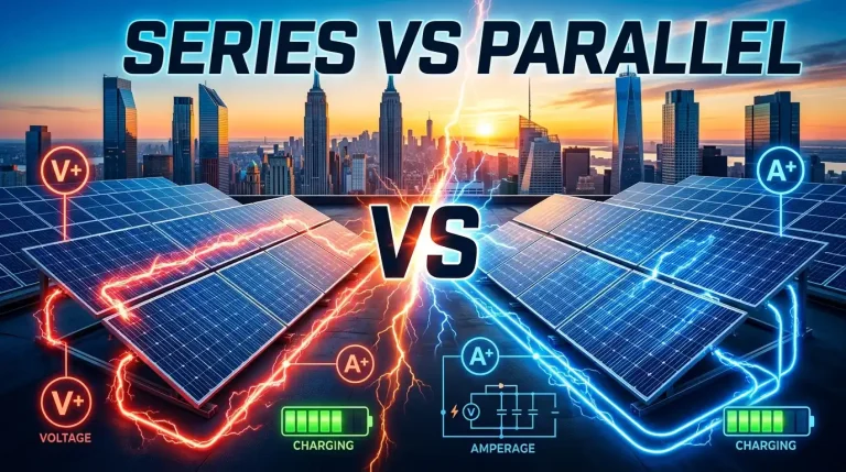
4. Series vs Parallel Solar Panel Wiring: Complete Comparison
This is the most asked question in DIY solar: solar panel wiring series vs parallel — which should you choose? The answer depends on your system voltage, charge controller type, shading conditions, and cable run length.
⚡ Series Wiring
- Voltages add up (e.g., 3×30V = 90V)
- Current stays the same
- Thinner, cheaper wire for long runs
- Requires MPPT charge controller
- One shaded panel hurts whole string
- Best for: grid-tied, MPPT off-grid, long cable runs
- Higher voltage = more electrical hazard risk
🔋 Parallel Wiring
- Current adds up (e.g., 3×10A = 30A)
- Voltage stays the same
- Thicker, more expensive wire needed
- Works with PWM or MPPT controller
- Shade-tolerant — independent panel output
- Best for: 12V RV, van, small off-grid systems
- Lower voltage = safer for DIY installers
| Factor | Series Wiring | Parallel Wiring | Series-Parallel |
|---|---|---|---|
| Voltage output | Multiplied (adds per panel) | Same as 1 panel | Moderate increase |
| Current output | Same as 1 panel | Multiplied (adds per panel) | Moderate increase |
| Charge controller | MPPT required | PWM or MPPT | MPPT recommended |
| Wire gauge needed | Thin (10–12 AWG) | Thick (6–8 AWG) | Medium (8–10 AWG) |
| Shade tolerance | Poor | Excellent | Good |
| Best system type | Grid-tied, large off-grid | 12V RV, van, cabin | Most 4+ panel systems |
| Safety | Higher voltage hazard | Safer (lower voltage) | Moderate |
5. Series-Parallel Wiring: Best of Both Worlds
Wiring solar panels in series and parallel (series-parallel or “hybrid”) combines both methods — panels are first grouped into series strings, then those strings are wired in parallel. This gives you moderate voltage AND moderate current, perfectly matched for most MPPT charge controllers.
Series-Parallel Example (4 Panels, 2S2P)
String 2: [P3: 30V/10A]─(series)─[P4: 30V/10A] = 60V / 10A
Strings 1+2 in parallel: 60V / 20A / 1200W
Voltage = series stack (60V) | Current = parallel sum (20A)
For wiring solar panels series vs parallel decisions on systems with 4+ panels: series-parallel is almost always the optimal choice. It keeps voltage high enough for efficient MPPT operation while keeping current manageable for reasonable wire sizes.
6. 12V Solar Panel Wiring Diagram
A 12V solar panel wiring diagram is the most common configuration for RVs, boats, camper vans, and small off-grid cabins. The goal is to keep system voltage at 12V to match the battery bank.
↓ (+) and (−) combined via MC4 Y-connectors
↓ 10 AWG solar panel cable
[Fuse/Breaker] → [MPPT or PWM Charge Controller]
↓ Battery terminals
[12V Battery Bank] → [Fuse] → [DC Loads (lights, fan, USB)]
[12V Battery Bank] → [Fuse] → [Inverter] → [120V AC Loads]
12V Wiring Rules
- Use parallel wiring for 12V panels going to a 12V battery — keeping voltage at 12V (technically ~18V Vmp which the controller handles)
- A PWM controller is the budget choice for 12V; MPPT is 10–30% more efficient but costs more
- Use a 10 AWG wire for solar panels on runs up to 30 feet; use 8 AWG for 30–50 feet
- Always add a fuse within 12 inches of the battery’s positive terminal
- A 12 volt solar panel wiring diagram PDF can be downloaded from Renogy, Victron, or Battle Born Batteries websites for your specific controller model
7. 24V Solar Panel Wiring Diagram with Converter, Charger & Inverter
A 24V solar panel diagram with converter, charger, and inverter diagram is the standard for medium-sized off-grid homes, larger cabins, and efficient RV builds. A 24V system cuts current in half vs. a 12V system of the same wattage, meaning smaller wires and less heat loss.
[12V Panel 1]─(+→−, series)─[12V Panel 2] = 24V string
Option B: 24V panels in parallel:
[24V Panel 1]─(parallel)─[24V Panel 2] = 24V, 2× amps
↓ 10 AWG PV cable to charge controller
[MPPT Charge Controller] ← accepts 24V–100V input, outputs 24V to batteries
↓
[24V Battery Bank] (two 12V batteries in series)
↓ ↓
[DC-DC Converter] [24V→120V Inverter]
(24V→12V for 12V loads) (for standard AC appliances)
24V Wiring Key Points
- To build a 24V battery bank: wire two 12V batteries in series (+ of battery 1 to − of battery 2)
- Use an MPPT charge controller — it handles the variable voltage from series-connected panels efficiently
- A DC-DC converter (24V to 12V) lets you power 12V devices from a 24V system without losing efficiency
- A 24V to 120V inverter/charger combo unit (like Victron MultiPlus or Renogy 2000W) handles both inversion and battery charging from shore power in a single box
- This is the diagram configuration for the popular “24V solar panel diagram with converter charger and inverter diagram” search — the charger refers to the MPPT controller, the converter is for 12V loads, and the inverter handles AC loads
8. RV Solar Panel Wiring Diagram
An RV solar panel wiring diagram must account for the unique constraints of mobile solar: space limitations, vibration, multiple load types (12V DC and 120V AC), and the need for a shore power connection alongside solar charging.
↓ 10 AWG PV wire in conduit
[MPPT Charge Controller] ← PV input
[MPPT Charge Controller] → battery output
↓ 4 AWG or larger cable (short run)
[Fuse Block / Busbar] → [12V Battery Bank (AGM or LiFePO4)]
↓ ↓ ↓
[DC Fuse Block] [Shore Charger] [Inverter/Charger]
(12V lights/fan) (hookup charging) (120V AC outlets)
Key differences in an rv solar panel wiring diagram vs. a home system:
- Add a rooftop disconnect switch — allows safe de-energizing of roof panels without going on the roof
- Run wires through a cable entry gland (watertight fitting) — never bare holes in the roof
- Use a battery disconnect switch for safe storage when the RV is parked long-term
- Include a shore power connection (converter/charger) for campsite hookup — wired to the same battery bank as the solar
- All wiring inside the RV should be in conduit or secured every 18 inches with wire clips to prevent chafing from road vibration
9. Wiring Solar Panel to Battery: Step-by-Step
Wiring solar panel to battery directly (without a charge controller) is only safe for very small trickle-charging applications like a 5W maintainer on a car battery. For any real solar system, you must use a charge controller between the panels and battery. Here’s the correct wiring sequence for how to wire a solar panel to a battery:
-
1
🔋 Connect Charge Controller to Battery First
Always connect battery to charge controller before connecting panels. This sequence is critical — connecting panels first can fry the controller’s input circuitry. Run correctly fused cables from the battery’s positive terminal to the controller’s “BAT+” input and negative to “BAT−”.
-
2
⚙️ Configure the Controller
Set the battery type (lead-acid, AGM, lithium) and voltage (12V or 24V) on the charge controller before connecting panels. Incorrect settings will overcharge and damage your battery bank.
-
3
☀️ Connect Panels to Charge Controller
Now connect your solar panel wire or solar panel extension cable from the panels to the controller’s “PV+” and “PV−” inputs. The controller will begin charging. Check the display to confirm voltage and current readings are as expected.
-
4
🔌 Connect DC Loads and Inverter
Wire DC loads to the controller’s load terminals (for small loads) or directly to the battery with an inline fuse. Connect the inverter directly to the battery with appropriately sized cable — a 1000W inverter needs minimum 4 AWG cable; a 2000W inverter needs 2 AWG.
For wiring solar panel to battery without a controller (trickle charge only): connect the panel positive directly to the battery positive with a blocking diode in-line, and negative to negative. This prevents battery discharge back through the panel at night. This setup is only safe for panels under 5W.
10. Solar Panel Wire Size Guide: 10 AWG, 12 AWG & the Calculator
Choosing the correct wire for solar panels is a critical safety and efficiency decision. Undersized wire overheats, causes voltage drop, and is a fire hazard. Oversized wire is unnecessarily expensive. Here’s how to size your wire correctly.
Solar Panel Wire Size Calculator Formula
Step 2: Find Total Wire Length = one-way distance × 2 (round trip)
Step 3: Calculate Voltage Drop = (Current × Wire Length × 0.0164) ÷ Wire Cross-Section
Step 4: Select AWG that keeps voltage drop under 2% of system voltage
Example (10A system, 30ft one-way = 60ft total, 12V system):
Max current = 10A × 1.25 = 12.5A
Voltage drop with 10 AWG = (12.5 × 60 × 0.0164) ÷ 5.26 = 2.34% → borderline, use 8 AWG for 30ft runs
Voltage drop with 10 AWG on 15ft run = (12.5 × 30 × 0.0164) ÷ 5.26 = 1.17% ✅ Safe
AWG Wire Size Reference Table for Solar Panels
| Wire Size | Max Amps (outdoor) | Max Run (12V, 2% drop) | Max Run (24V, 2% drop) | Best Use |
|---|---|---|---|---|
| 14 AWG | 15A | 10 ft | 20 ft | Very small systems only |
| 12 AWG | 20A | 15 ft | 30 ft | Small 100–300W systems, short runs |
| 10 AWG wire for solar panels | 30A | 25 ft | 50 ft | Most common residential choice |
| 10 gauge wire for solar panel | 30A | 25 ft | 50 ft | Same as 10 AWG (gauge = AWG) |
| 8 AWG | 40A | 40 ft | 80 ft | High-current parallel systems, longer runs |
| 6 AWG | 55A | 65 ft | 130 ft | High-current parallel arrays, inverter connections |
| 4 AWG | 70A | 100 ft | 200 ft | Battery-to-inverter connections, large arrays |
10 AWG Solar Panel Wire: The Standard Choice
10 AWG wire for solar panels (also written as 10 gauge solar panel wire or 10 AWG solar panel wire) is the most widely used size in residential and RV solar installations. It handles up to 30A safely and is appropriate for panel-to-controller runs up to 25 feet in 12V systems and 50 feet in 24V systems. Most pre-made solar panel extension cables are sold in 10 AWG as the standard.
PV wire for solar panels (specifically rated USE-2 or UL 4703 PV Wire) is the correct outdoor-rated cable type. It has a thicker, UV-stabilized jacket that resists degradation from years of rooftop sun exposure. Never substitute with standard electrical wire for any outdoor solar run.
11. Solar Panel Extension Cables & MC4 Electrical Connectors
Solar Panel Extension Cable
A solar panel extension cable extends the reach of your panel leads to the charge controller or combiner box. Panel leads are typically only 3–4 feet long — a solar panel cable extension bridges the gap when your controller is 15–50 feet from the panels.
Key things to know about solar panel extension cables:
- Always buy 10 AWG solar extension cable for most systems — it’s the standard size that fits MC4 connectors and handles typical system currents
- Both ends come pre-fitted with MC4 connectors — they plug directly into panel leads and controller input cables
- Available in lengths from 5 feet to 50+ feet. For runs over 50 feet, order custom-length cable or splice with properly rated wire and weatherproof connectors
- Extension cables for solar panels must be UV-rated PV wire — standard extension cords are NOT suitable outdoors on a roof
- Buy the correct polarity: one cable with a male MC4 on one end for the positive run, one with female MC4 for the negative run
- Cable panel solar kits (sold as pairs) include both positive and negative extension cables — the most convenient buying format
MC4 Solar Panel Electrical Connectors
Solar panel electrical connectors — specifically MC4 connectors — are the universal standard in the solar industry. Every modern solar panel comes with pre-installed MC4 connectors on its output leads.
MC4 Male Connector
Fitted on positive leads. Has a protruding pin inside the housing. Connects to female MC4.
MC4 Female Connector
Fitted on negative leads. Has a socket inside the housing. Receives the male pin.
MC4 Y-Branch (Parallel)
Splits one wire into two — used to connect multiple panel leads together for parallel wiring. Also called MC4 parallel adapters.
MC4 Extension Connectors
Male+female pair used to extend cable length between panel and controller. Pre-crimped or field-termination versions available.
Solar Panel Wires and Connectors: Key Rules
- Never mix MC4 brands — Stäubli (original MC4), Amphenol, and generic brands have slightly different tolerances. Mismatched connectors cause poor contact, arcing, and heat buildup.
- Solar panel wire connectors must be fully latched — push until you hear/feel a click. A partially inserted MC4 has high contact resistance.
- Use an MC4 disconnect tool to separate connectors — never pull on the cable or pry with a screwdriver, which damages the connector body.
- Inspect solar panel wiring connectors annually for corrosion, discoloration, or melting — these are signs of a poor connection that needs immediate attention.
- Solar panel cables and connectors rated for 30A (10 AWG with MC4) handle any standard residential panel (up to 400W at standard voltages).
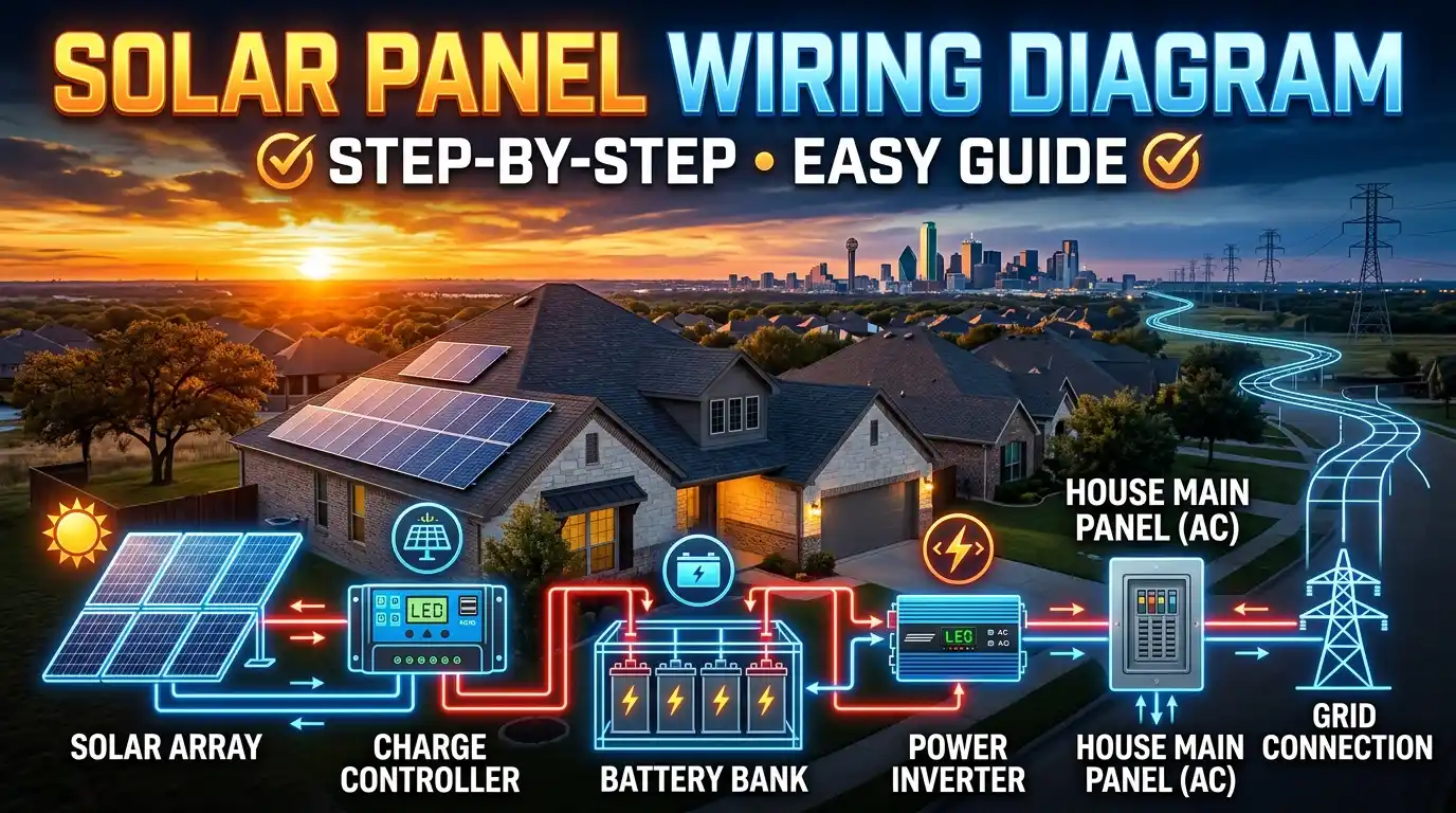
12. Full Solar Panel System Diagram: Panels to Inverter
Here is the complete diagram of solar panel system — also known as a solar panel installation diagram — showing every component connection from panels to household loads. This is the reference diagram for a typical off-grid or hybrid system.
↓
[DC Disconnect Switch] (NEC required)
↓
[MPPT Charge Controller] (e.g. Victron SmartSolar, Renogy Rover)
↙ ↘
[Battery Bank] [System Monitor / BMS]
(12V/24V/48V)
↓ fused positive
[Inverter / Inverter-Charger] (DC→AC conversion)
↓ 120V AC output
[AC Sub-Panel] ─▶ [Household Loads]
Optional: Grid/Shore Power → Inverter-Charger → Battery (hybrid charging)
A solar panel diagram how it works can be summarized as: sunlight hits panels → DC electricity flows through charge controller → battery charges → inverter converts DC to AC → powers your home. The solar panel schematic diagram adds safety disconnects, fuses, and monitoring at each stage.
A solar panel installation diagram PDF for your specific controller model is available free from manufacturer websites: Victron Energy, Renogy, Schneider Electric, and Outback Power all publish detailed PDF wiring guides for download.
13. Electrical Panel Upgrade for Solar & Solar Ready Electrical Panel
For grid-tied solar systems, your home’s electrical panel must be able to accept the solar inverter’s AC output. Two common scenarios homeowners encounter:
Electrical Panel Upgrade for Solar
An electrical panel upgrade for solar is needed when:
- Your current panel is a 100A service — most solar installers require 200A service for a system over 5kW. Upgrading to 200A costs $1,500–$4,000 and is done by a licensed electrician.
- Your panel is full with no available breaker slots — solar requires a dedicated breaker (typically 40A–60A for a 7–10kW system). If no slots exist, a panel upgrade or sub-panel addition is needed.
- Your panel uses outdated or recalled breaker brands (Federal Pacific Stab-Lok, Zinsco) — solar installers and inspectors will typically require replacement before approving the solar connection.
- The panel is too old (30+ years) for warranty-compliant solar interconnection
Solar Ready Electrical Panel
A solar ready electrical panel is a main electrical panel designed with dedicated conduit knockouts, reserved breaker spaces, and pre-wired connection points for future solar installation. These panels significantly reduce the cost and complexity of adding solar later. Brands like Square D (QO Series), Leviton, and Siemens offer solar-ready panels. If you’re building a new home, always specify a solar-ready panel — it costs $50–$200 more upfront and saves $500–$1,500 when solar goes in.
For a solar panel with electrical outlet setup (connecting solar directly to a standard outlet for plug-in appliances), a micro-inverter grid-tie system or portable solar generator (like EcoFlow or Jackery) is the correct approach — never wire solar panels directly to a wall outlet, as this is a code violation and fire hazard.
14. Solar Panel Wiring Kit: What’s Included & What to Buy
A solar panel wiring kit bundles the most commonly needed wiring components into one purchase. This is the easiest way for DIY installers to get started without sourcing every component separately.
What a Solar Panel Wiring Kit Typically Includes
- Solar panel extension wire — usually 20–50 feet of 10 AWG PV cable, red and black
- MC4 connectors — pre-crimped pairs (male/female) on each cable end
- MC4 Y-branch connectors — for parallel wiring of 2–4 panels
- Inline fuse holders — for overcurrent protection on each string
- Cable ties and mounting clips — for securing cables to the roof or mounting rails
- Some kits include an MC4 disconnect tool and a solar panel wiring connectors crimping tool
Best Solar Panel Wiring Kits (by Use Case)
| Kit Type | Best For | Typical Price | What to Look For |
|---|---|---|---|
| Basic 2-panel kit | RV, shed, small off-grid | $25–$45 | 10 AWG PV wire, MC4 connectors, inline fuse |
| 4-panel series-parallel kit | Off-grid cabin, larger RV | $50–$80 | Includes Y-branch connectors, combiner fuses |
| Complete wiring kit (panels + controller) | Full DIY system builders | $80–$150 | Includes MC4 tool, wire stripper, full cable set |
| Renogy Solar Wiring Kit | Renogy panel owners | $35–$60 | Pre-matched for Renogy panels and controllers, 10 AWG |
Solar panels wiring mistakes are the #1 cause of DIY system failures. A complete kit ensures you have correctly rated components that are designed to work together. Buy from reputable brands (Renogy, BougeRV, HQST) rather than unbranded kits from unknown sellers on Amazon.
15. Frequently Asked Questions
Parallel wiring: Connect all positive terminals together (via MC4 Y-connectors) and all negative terminals together. Currents add, voltage stays the same. Best for 12V/24V battery systems and shaded locations.
For 4+ panels, use series-parallel — group panels into series strings, then wire the strings in parallel. This gives moderate voltage and moderate current — the best balance for most MPPT charge controllers.
⚡ Solar Panel Wiring: Key Takeaways
- Series wiring adds voltage, keeps amps same — use with MPPT, best for long cable runs
- Parallel wiring adds amps, keeps voltage same — use for 12V/24V battery systems
- Series-parallel is optimal for most 4+ panel systems — balanced voltage and current
- Always use 10 AWG PV-rated stranded copper wire for standard residential runs
- MC4 connectors are universal — never mix brands in the same system
- Solar panel extension cables must be UV-rated PV wire — not standard extension cords
- Always connect battery to controller first, then panels — never panels first
- A charge controller is required for any system above 5W — never wire panels directly to battery
- Grid-tied systems may need an electrical panel upgrade — check with a licensed electrician
- Free solar panel wiring diagram PDFs are available from Renogy, Victron, and NREL